IA-780i FPGA Accelerator with Intel Agilex 7 FPGA
IA-780i 400G + PCIe Gen5 Single-Width Card Compact 400G Card with the Power of Agilex The Intel Agilex 7 I-Series FPGAs are optimized for applications
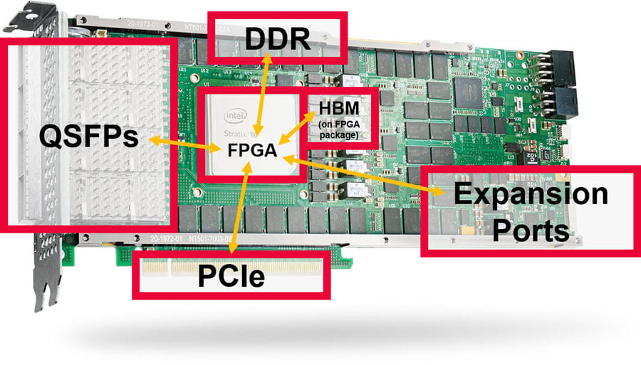
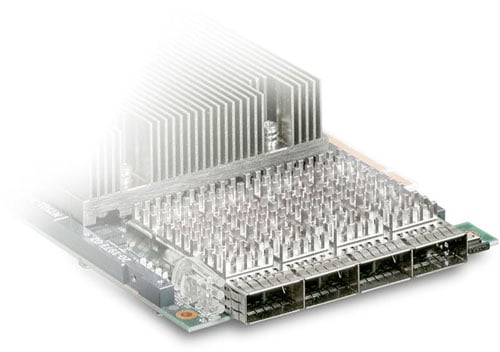
Large FPGAs, such as the Stratx 10 and Agilex series from Intel, feature a wide array of I/O interfaces. BittWare provides cards that make use of these by providing features like QSFPs, PCIe, on-card DDR4 and GDDR6 memory and expansion ports. We also have cards featuring FPGAs with on-package HBM2.
Accessing all these interfaces is not simple, particularly if resources are required to be shared between multiple kernels. FPGAs have no built-in cache or arbitration logic beyond basic memory controllers—arbitration is the responsibility of the user.
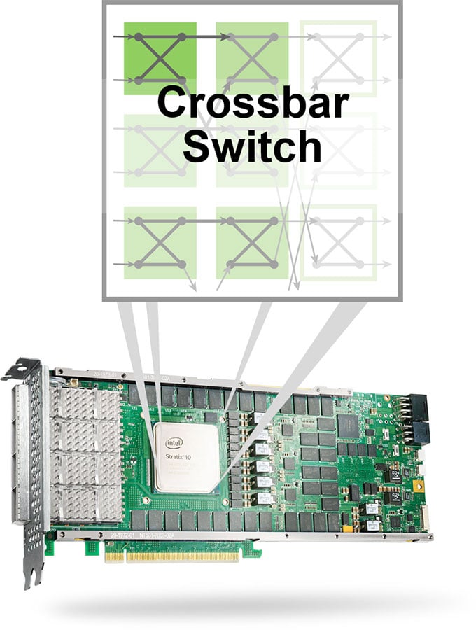
One solution to sharing connectivity between multiple kernels and multiple interfaces is a crossbar switch. This can be creating using FPGA native programming, of course. However, if we use a high-level programming language like oneAPI we can easily optimize it to be as efficient as possible based on the number of connections required and the width of the interfaces.
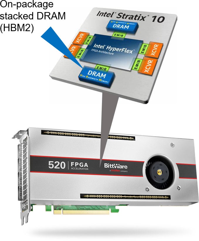
The BittWare Butterfly Crossbar Switch was developed on our 520N-MX card, which features HBM2 memory and multiple network ports.
A crossbar is a collection of switches arranged in a matrix. It reduces the connections required between a group of inputs/outputs.
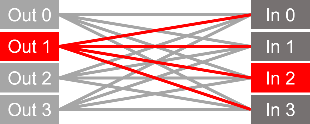
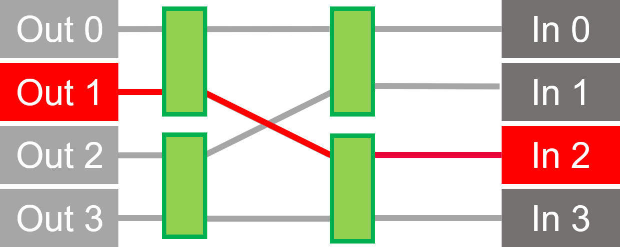
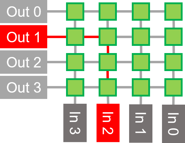
The matrix is equal to the number of inputs multiplied by the number of outputs.

Matrix size is N x log2(N) / 2, where N is number of inputs.
We chose Butterfly because it uses less FPGA resources. However, it can have reduced throughput in some cases.
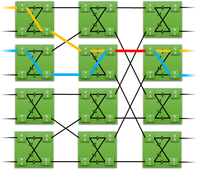
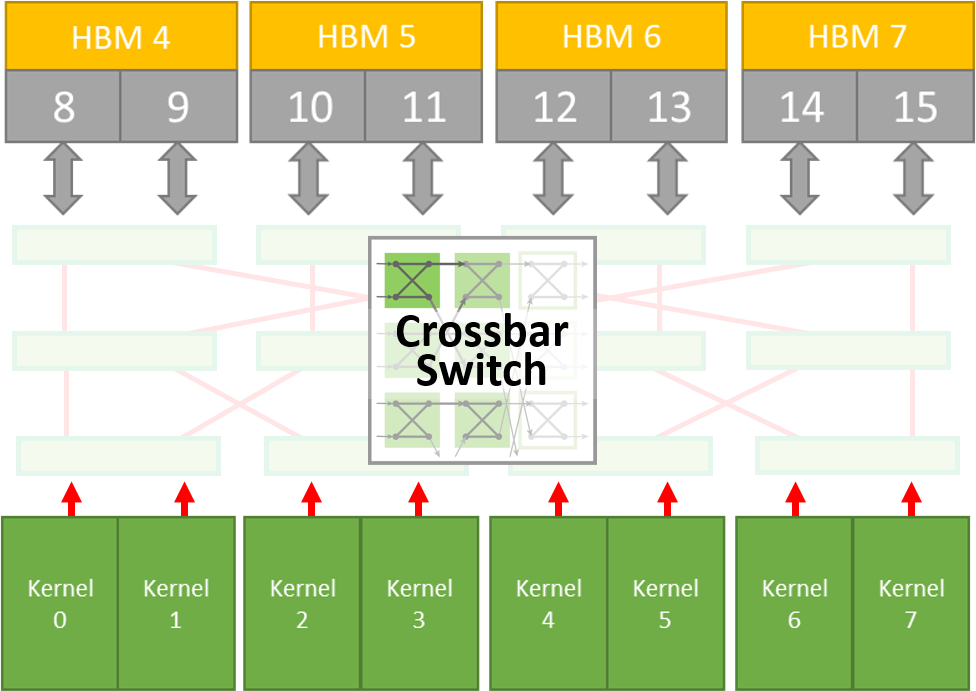
In this example of a butterfly crossbar, 8 inputs are routed to 8 outputs using just 12 switches. Each switch has two inputs and two outputs. The data is routed straight through or switched to the opposite route.
If only one path is switched, then there can be a clash at an output and the switch must arbitrate who has access to the path. Arbitration uses a simple ping pong scheme by default, although more sophisticated schemes could easily be implemented if required.
By utilizing high level languages (DPC++), the crossbar switch can be tailored for a particular application requirement—for example:
This allows designs to be optimized for resource. Power is kept to a minimum by removing the need for an always active built-in generic switch.
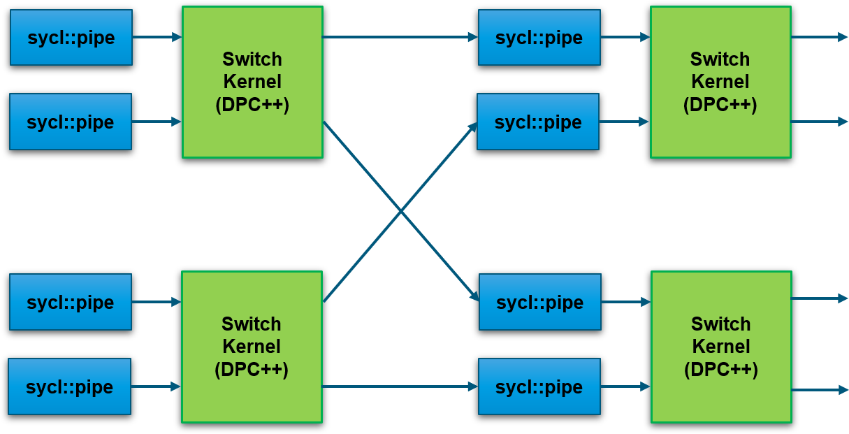
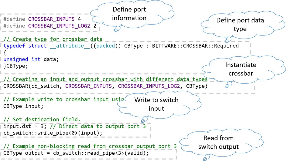
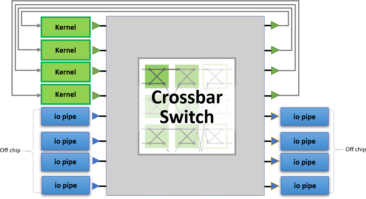
oneAPI abstracts the interface between the host and FPGA. Interfaces with external I/O (such as QSFPs in the diagram) are also abstracted using oneAPI I/O pipes. This allows designs to be scaled out to multiple BittWare FPGA cards which support oneAPI.
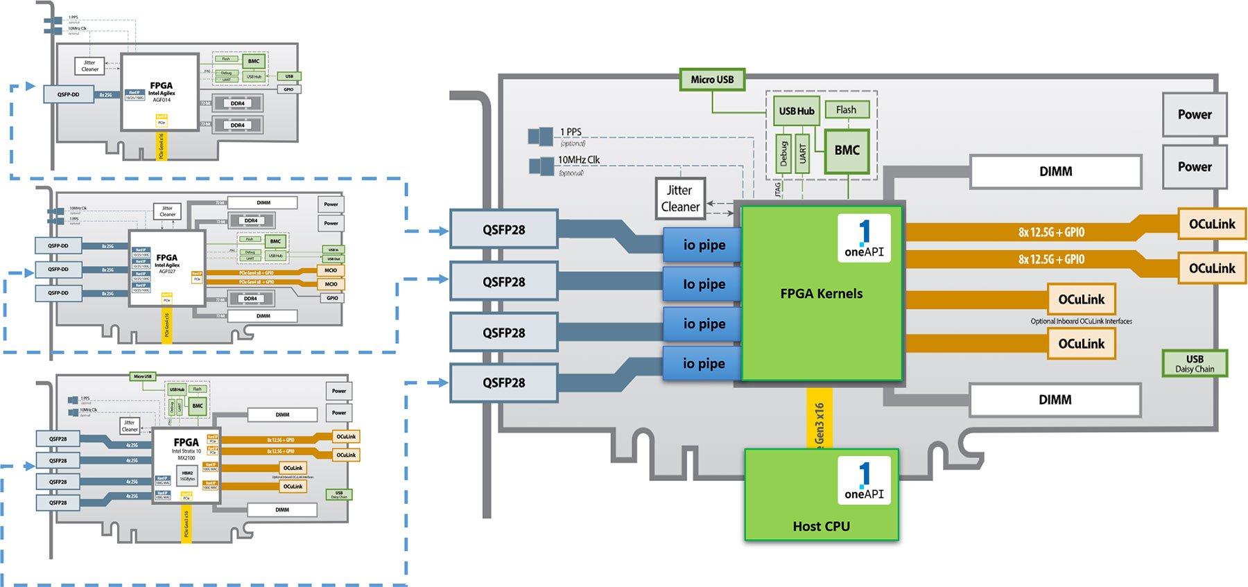
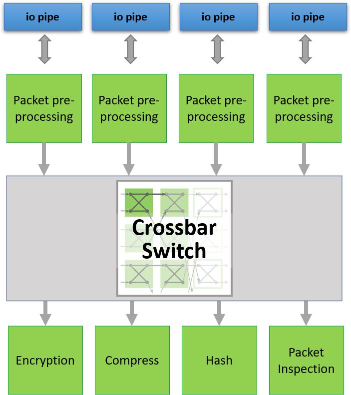
A crossbar switch can be used to direct packets to or from network ports. Here, a small modification to the DCP++ code changes arbitration to be on network packet boundaries.
With the Crossbar Switch, we can optimize kernels that need to share access to HBM2 memory channels.
Each port has peak throughput of 12.8 GBytes/Sec.
Each port has access to only 512 MBytes of memory
16 GBytes in total
Our Crossbar Switch can address these problems to improve performance.
Without Crossbar: Large number of routes using multiplexing approach (no arbitration).
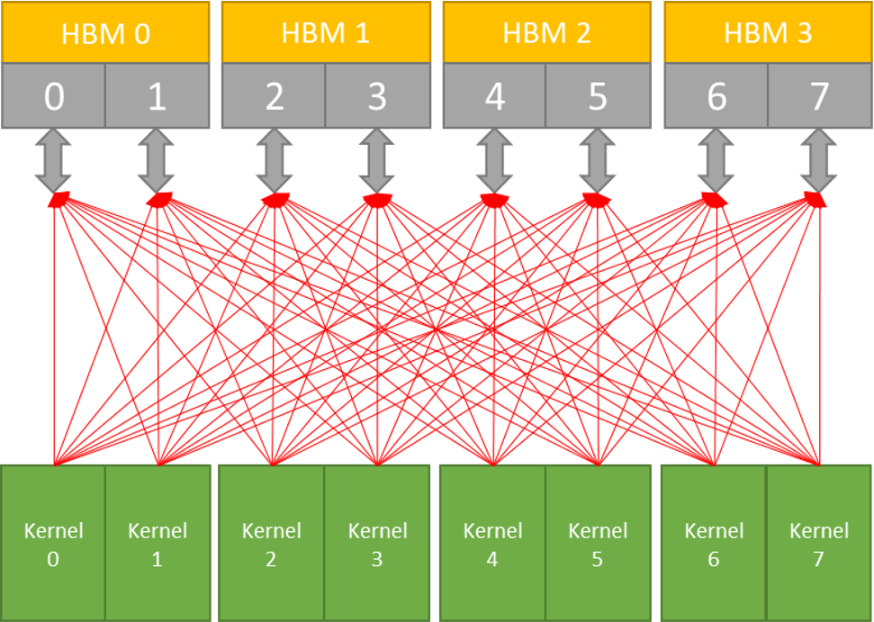
Our Butterfly Crossbar Switch reduces routing and adds arbitration for higher performance.
You can request the BittWare Butterfly Crossbar Switch by filling out this form. Our sales team will connect with you for the next steps to accept the license agreement and set up a log in to download the code.
"*" indicates required fields
IA-780i 400G + PCIe Gen5 Single-Width Card Compact 400G Card with the Power of Agilex The Intel Agilex 7 I-Series FPGAs are optimized for applications

White Paper FPGA-Accelerated NVMe Storage Solutions Using the BittWare 250 series accelerators Overview In recent years, the migration towards NAND flash-based storage and the introduction

PCIe Gen4 data mover IP from Atomic Rules. Achieve up to 220 Gb/s using BittWare’s PCIe Gen4 cards, saving your development team when you need more performance than standard DMA. Features: DPDK and AXI standards, work with packets or any other data format, operate at any line rate up to 400 GbE.

Article FPGA Neural Networks The inference of neural networks on FPGA devices Introduction The ever-increasing connectivity in the world is generating ever-increasing levels of data.