Webinar: HPC with Next-Generation Intel Agilex FPGAs
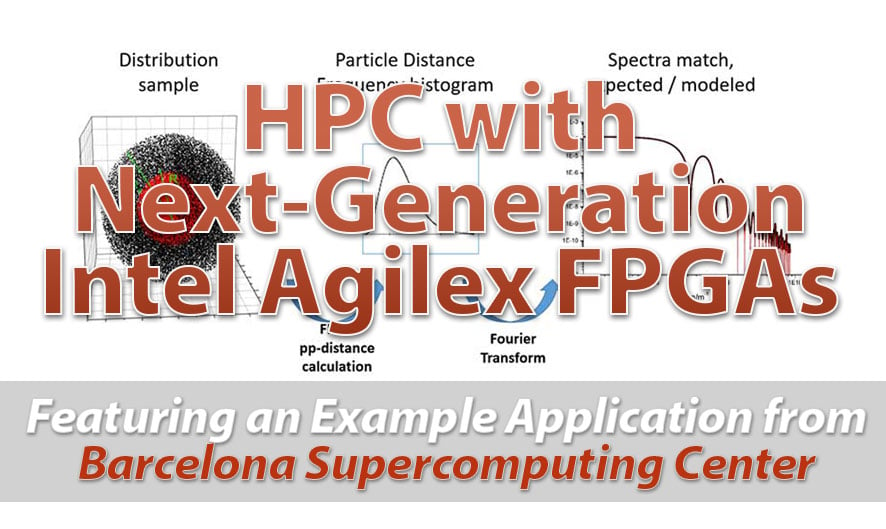
BittWare On-Demand Webinar High Performance Computing with Next-Generation Intel® Agilex™ FPGAs

BittWare On-Demand Webinar High Performance Computing with Next-Generation Intel® Agilex™ FPGAs
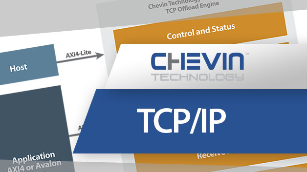
Go Back to IP & Solutions TCP/IP Offload Ethernet IP The TCP/IP (Transmission Control Protocol/ Internet Protocol) is an Ethernet IP core for FPGAs that
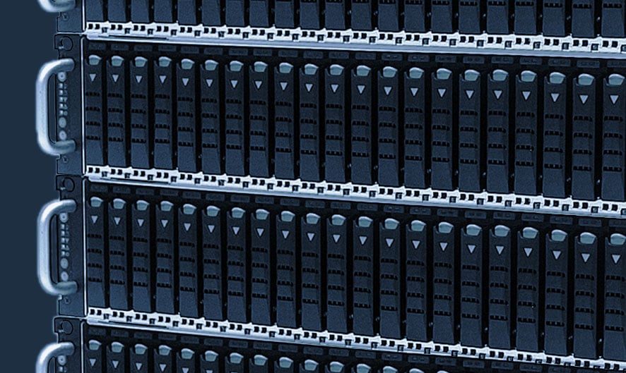
White Paper Building NVMe Over Fabrics with BittWare FPGA Solutions Overview Since the introduction of the Non-Volatile Memory Express (or NVMe) protocol, data center customers
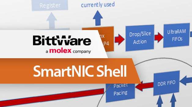
White Paper Introduction to BittWare’s SmartNIC Shell for Network Packet Processing Overview SmartNIC Shell is a complete working NIC that is implemented on a BittWare